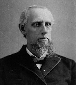
Amos
Dolbear
|
Amos
Emerson Dolbear, est né le 10 novembre 1837 à
Norwich dans le Connecticut et mort le 23 février
1910, Dolbear
a étudié la conversion d'allumage électrique
en ondes sonores et impulsions électriques. |
J'ai trouvé des traces imprécises ou contradictoires
comme :
- En 1865 Encore étudiant, Dolbear
envisage l'idée de développer un télégraphe
en remplaçant les batteries par des aimants permanents.
«Une tradition vivante» raconte que le Dr.Dolbear et un compagnon
ont installés des récepteurs et un fil du sous-sol à
l'étage supérieur de la Chapelle Thomson et la voix humaine
a été transmise, les premiers mots étaient «
Pouvez-vous m'entendre ? »
- En 1868 Amos Dolbear, alors professeur à Bethany College,
a inventé le «téléphone électrostatique».
Dolbear prétend avaoir
inventé le premier récepteur téléphonique
contenant deux fonctions du téléphone moderne (un aimant
permanent et une membrane métallique faite à partir d'un
ferrotype) en 1865, soit 11 ans avant qu'Alexander Graham Bell ait fait
breveter son modèle.
Dolbear ne pourra prouver sa réclamation, si bien que le brevet
de Bell est maintenu. Il perd devant la Cour suprême des États-Unis
(Dolbear contre American Bell Telephone Company). L'édition du
18 juin 1881 de la revue Scientific American rapporte : « si [Dolbear]
avait été attentif aux formalités du bureau des brevets,
il est possible que le téléphone parlant, aujourd'hui si
largement crédité à M. Bell serait recueilli parmi
ses propres lauriers ».
En 1874 Bell, attiré par l'idée de transmettre la voix, alors qu'il était en travaux sur le "Télégraphe Multiple", concrétise "Le Téléphone" en 1876.
En 1876, Dolbear brevette un téléphone électrique avec magnéto. Il fait breveter un téléphone statique en 1879 et en 1881 un téléphone électrostatique à condensateur2. En 1882, Dolbear était en mesure de communiquer sur une distance de 400 mètres sans fil en terre. Son dispositif s'appuie sur la conduction électrique dans le sol, qui est différente des transmissions radio ultérieures qui utilisent le rayonnement électromagnétique. Il reçoit un brevet américain pour un télégraphe sans fil en mars de cette même année. Son installation utilise des téléphones reliés au sol par des tiges métalliques plantées en terre. La portée de transmission est d'au moins 800 mètres. Il obtient un brevet pour cet appareil, le (en) Brevet U.S. 350299 [archive], en 18863,4 (il n'a pas breveté son système en Europe).
15 janvier
1876 Après avoir fait parler son premier
téléphone Brevet
174,465 , Bell
dépose un deuxième brevet US
186 787 : la box
Les avocats de Bell le pressent de rédiger
des spécifications et déposent à Washington le deuxième
brevet sur le téléphone incluant les différentes
améliorations. Il est attribué deux semaines plus tard sous
le no US 186 787 dont voici une
reproduction :
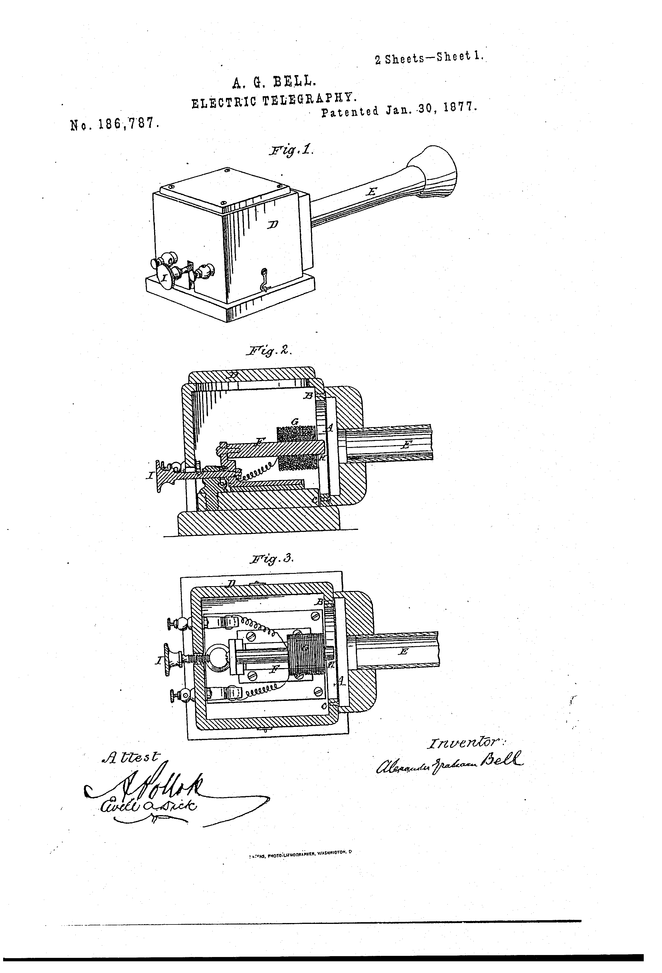 et
et 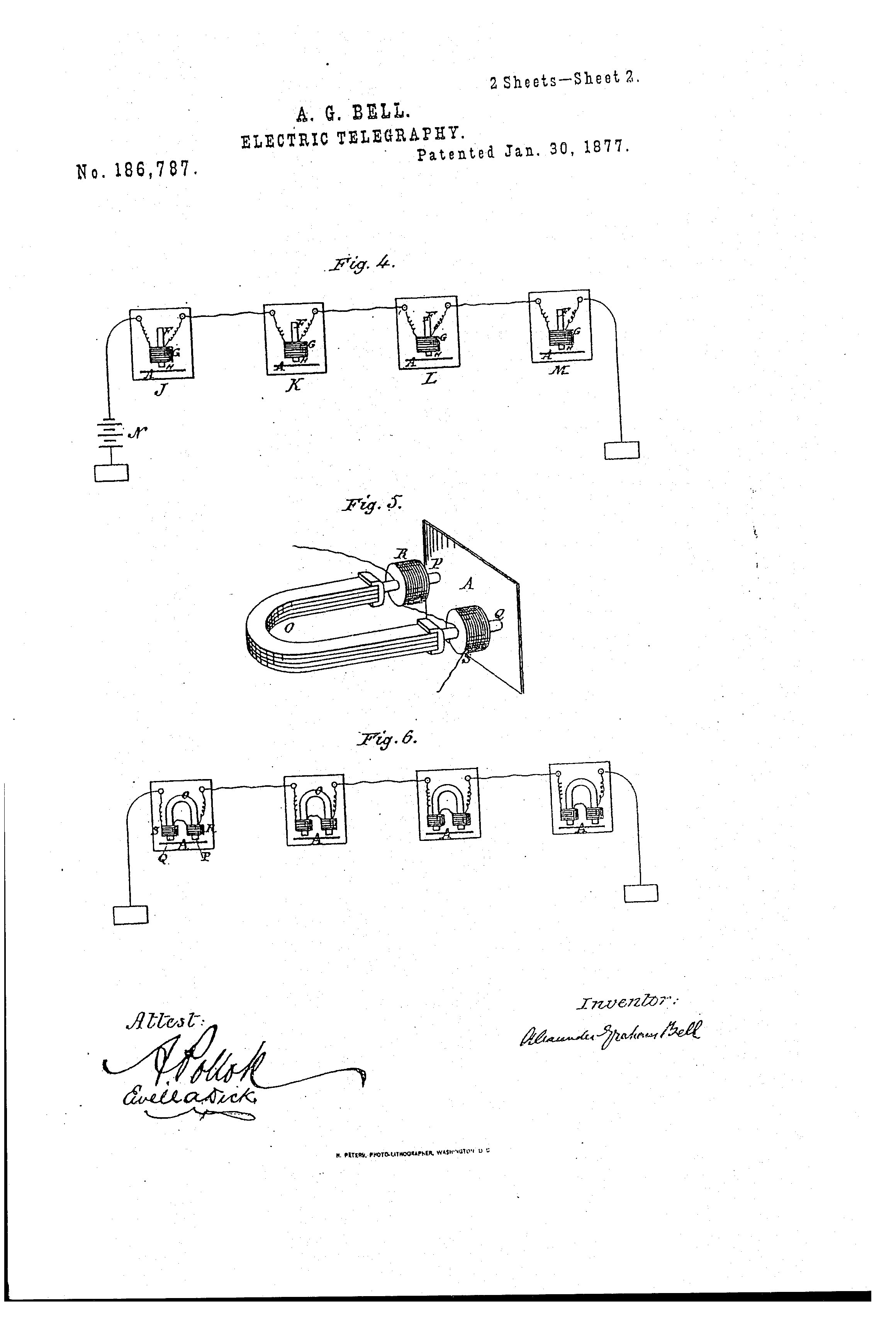 ( en pdf )


Ce téléphone volumineux est une encore une
boite disgracieuse (sauf pour les collectionneurs), de plus il n'y avait
pas encore de dispositif tel qu'une sonnerie ou un avertisseur sonore
pour attirer l'attention de la personne à la réception d'un
appel. Il fallait taper fortement avec un crayon sur le diaphragme ou
hurler devant l'embouchure. Son utilisation était désagréable:
il fallait prendre la boite et crier, puis la porter à l'oreille
pour écouter.
Malgré ces problèmes, Bell et son groupe ont décidé
de commercialiser entièrement l'invention.
En 1877 Dolbear,
apporte deux améliorations importante au téléphone
de Bell
- l'utilisation d'aimants permanets dans les transmetteurs et les récepteurs,
ce qui permet de s'affranchir de la batterie dans le circuit.
- le remplacement de la menbrane par un disque en acier
C'est en septembre 1876 que lui vient cette idée mais il tarde
à la mettre en pratique.
En janvier 1876 Dolbear apprend que Bell a déposé une
demande le 15 janvier 1877 de brevet le concernant, mais ne donne
pas de suite sur ce point
Fin 1877 Dolbear édite son livre "The
Telephone"
 Reproduction
Dolbear
Dépose un brevet le 6 Decembre 1877, TELEPHONE Patent
US 199 041 approuvé le 8 Janvier 1878
 Bell
avait il été au courant de cette améloiration et
en a t'il tiré parti ?
Dolbear revendique l'invention du téléphone devant
les tribunaux, il ne pourra prouver sa réclamation.
Au procès les
avocats de Dolbear ont eut la mauvaise idée d'amener un téléphone
de Reiss pour lui en donner la patérnité, ce qui priverait
Bell de ce privilége. Mais l'appareil refuse de fonctionner.
C'était encore un système de type télégraphique
à rupture du courant et non pas courant de modulation produit par
la voix.
Dans le jugement en 1883 le juge décrète que Bell a breveté
la véritable idée de transmission de la parole par l'électricité
....
Le brevet de Bell sera maintenu.
Pourtant l'édition du 18 juin 1881 de la revue "Scientific
American" rapporte : « si [Dolbear] avait été
attentif aux formalités du bureau des brevets, il est possible
que le téléphone parlant, aujourd'hui si largement crédité
à M. Bell serait recueilli parmi ses propres lauriers ».
Dolbear est un scientifique, il continuera longtemps
à travailer sur "la transmission du son"
Voici l'essentiel de ses travaux et brevets :
Le 30 Sept. 1979 Brevet US 220 205
"combinid speaking-telephone and morse sounder"
En 1881 Téléphone électrostatique à
condensateur, brevet US
239 742 A, 5 avril 1881

Brevet "Mode of Transmitting Sound by Electricity". US
240 578 26 Avr 1881


Article paru dans la revue SCIENCE pages 310 -12 et 13
En 1882, Dolbear était en mesure de communiquer sur une
distance de 400 mètres sans fil en terre.
Son dispositif s'appuie sur la conduction électrique dans le sol,
qui est différente des transmissions radio ultérieures qui
utilisent le rayonnement électromagnétique.
Il reçoit un brevet américain pour un télégraphe
sans fil en mars de cette même année.
Brevet SPECIFICATION TELEPHONE Patent No.
US 288 215, 13 Nov. 1883.
Brevet TELEPHONE RECEIVER Patent No US
355 149 28 Dec. 1886
Brevet MODE 0F ELECTRIC COMMUNICATIONPatent No
US350 299 5 Oct. 1886
Son installation utilise des téléphones reliés au
sol par des tiges métalliques plantées en terre. La portée
de transmission est d'au moins 800 mètres.
En 1899, le New England Wireless Telegraph
and Telephone Company, une filiale de la Wireless
Telephone and Telegraph Company américaine, achète
le brevet de 1886 de Dolbear et dépose une plainte contre Guglielmo
Marconi pour
contrefaçon dans une tentative infructueuse de concurrencer les
activités de télégraphie de Guglielmo Marconi aux
États-Unis. .
Toutefois, en mars 1901, un tribunal des États-Unis
rejette la poursuite.
En avril 1902, L'American Wireless lance une pétition
au Congrès pour prolonger le brevet de 1886 pour dix années,
mais sans succès, de sorte qu'il a dûment expiré le
4 octobre 1903.
En 1905, le tribunal de New York note en outre que le brevet de
Dolbear est « inopérant, et que, même s'il l'avait
été, il s'opère en vertu de lois et de phénomènes
électriques radicalement différents » de la radio
utilisée par Marconi.
Dolbear a également inventé un kaléidoscope
(un instrument de visualisation de vibrations d'ondes sonores, en utilisant
un miroir monté sur une membrane) et un système d'éclairage
à incandescence.
Il est aussi l'auteur de plusieurs livres, articles et brochures, et a
été reconnu pour ses contributions à la science à
la fois l'Exposition universelle de Paris et à la Crystal Palace
Exposition en 1882.
En 1897, Dolbear publie un article « Le cricket comme un
thermomètre » dans lequel il établit une corrélation
entre la température ambiante et la fréquence à laquelle
le grillon stridule, la formule développée dans cet article
est connue sous le nom loi de Dolbear.
sommaire
Dolbear a apporté de nombreuses inventions notables
au monde scientifique, notamment le téléphone, le gyroscope
électrique utilisé pour démontrer la rotation de
la Terre, l’opéidoscope et un nouveau système d'éclairage
à incandescence.
Il a publié plusieurs livres, articles et brochures, y compris
"Matter, Ether, Motion", et a été reconnu pour
ses contributions à la science à l'Exposition de Paris en
1881 et à l'exposition Crystal Palace en 1882.
Livres
The Art of Projecting, Boston, 1876
The
Speaking Telephone, 1877
Sound and its Phenomena, 1885
First Principles of Natural Philosophy, Boston, 1897
Modes of Motion, Boston, 1897
Matter, Ether, and Motion
Articles de journaux
The Cricket as a Thermometer, The American Naturalist,
vol. 31, no 371, novembre 1897, p. 970–971, publié par l'University
of Chicago Press pour l'American Society of Naturalists
_______________________________________________________________________
SPECIFICATION forming part of Letters Patent No. US
350 299 dated October 5, 1886.
Application filed March 24, 1882. Serial
No. 56,664. (No model.)

To all whom it may concern:
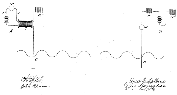
Be it known that I, AMOS EMERSON DOLBEAR, of Somerville, in the county of Middlesex and State of Massachusetts, have invented a new Mode of Electric Communication, of which the following is a full, clear, concise, and exact description, reference being had to the accompanying diagram, forming a part hereof.
My invention relates to establishing electric communication between two or more places without the use of a wire or other like conductor, and it consists in connecting the transmitting--instrument with a ground the potential of which is considerably above the normal, and the receiving--instrument with a ground the potential of which is considerably below the normal, the result being that an impulse from the transmitter sufficient to cause the receiver to give intelligible signals is transmitted through the earth without the need of any circuit, such as has heretofore been deemed essential.
In the diagram, A represents one place, (say Tuft's college,) and B a distant place, (say my residence.)
C is a wire leading into the ground at A, and D a wire leading into the ground at B.
G is a secondary coil, one convolution of which is cut, the ends thus formed being connected with the poles of the battery f', which has a number of cells sufficient to establish in the wire C1, which is connected with one terminal of the secondary coil G, an electro--motive force of, say, one hundred volts. G in this instance also represents an induction--coil, T being a microphone--transmitter, f its primary circuit, and f' its battery--that is, the battery f' not only furnishes the current for the primary circuit, but also charges or electrifies the secondary coil G and its terminals C and H'.
Now, if words be spoken in proximity to transmitter T, the vibration of its diaphragm will disturb the electric condition of the coil G, and thereby vary the potential of the ground at A, and the variations of the potential at A will cause corresponding variations of the potential of the ground at B, and the receiver R at B will reproduce the words spoken in proximity to transmitter T, as if the wires CD were in contact or connected by a third wire. Electric communication may be thus established between points certainly more than half mile apart; but how much farther I cannot now say.
There are various well--known ways of electrifying the wire C to a positive potential far in excess of a hundred volts and the wire D to a negative potential far in excess of a hundred volts.
In the diagram, H H' H1 represent condensers, the condenser H' being properly charged to give the desired effect. The condensers H and H1 are not essential, but are of some benefit; nor is the condenser H' essential when the secondary G is otherwise charged; I prefer to charge all these condensers, as it is of prime importance to keep the grounds of wires C and D oppositely electrified, and while, as is obvious, this may be done by either the batteries or the condensers, I prefer to use both.
The main difficulty in utilising my invention on a large scale is that when there are many spots corresponding to A and B signals transmitted from any A will go to the nearest B, or to several B's, depending upon proximity and other causes. One method of obviating this difficulty is to use a given A only during a certain assigned time for communicating with a certain B, the particular B being arranged to receive communications only during the assigned time. Thus, if there were ten B's within a given area, then the first B might be used for the first hour, the second B for the next hour, and so on, and the first A for the first five minutes of the first hour, the second A for the next five minutes, and so on, so that either one of the A's might have free communication with the first B, each for its assigned time during the first hour, and either A with the second B, each for its assigned five minutes of the second hour, and so on.
In practice there will be of course both a receiver and transmitter at A and B, proper switches being used to bring either into use, as will be well understood without description.
I have spoken only of telephone--instruments, as these give the best results; but any electric instruments may be used capable of utilizing the currents passing through the earth from C to D, and the strength of such currents can be largely increased by increasing the positive potential of C and the negative potential of D. It will also be obvious that if the end of coil G (shown in the diagram as connected with one armature of condenser H') be grounded, and the end shown grounded be connected with the condenser, then C will be minus, and D must therefore be made plus.
What I claim is--
The art above described of communicating by electricity, consisting in first establishing a positive potential at one ground and a negative at another; secondly, varying the potential of one ground by means of transmitting apparatus, whereby the potential of the other ground is varied; and, lastly, operating receiving apparatus by the potential so varied, all substantially as described.
AMOS EMERSON DOLBEAR.
